

Views: 0 Author: Site Editor Publish Time: 2026-10-11 Origin: Site


How does a self-driving car truly see? The answer lies in the invisible, rapid-fire processing of light. Light Detection and Ranging, commonly known as LiDAR, serves as the primary optical sensory system for advanced autonomous vehicles. It acts as the digital eyes that map the physical world in real-time. However, a self-driving car's vision is only as reliable as the data it can process.
Modern sensor systems generate massive amounts of high-frequency data, often operating in the multi-gigahertz spectrum. Transmitting this staggering volume of information from the sensor's photodetectors to the central processing unit without delay, distortion, or loss is a monumental engineering challenge. This discipline is known as maintaining signal integrity. Traditional organic substrates frequently fail under these extreme signal demands, succumbing to thermal stress and high-frequency attenuation. To overcome these physical limitations, engineers have turned to specialized materials. Integrating a high-performance Ceramic Circuit Board for LiDAR has become the industry gold standard for preserving flawless signal integrity in the harshest automotive environments.
This comprehensive guide explores the specific signal integrity demands of autonomous driving optical systems. Specifically, we unpack why ceramic substrates are not merely an upgrade, but an absolute necessity for engineers and manufacturers striving to meet uncompromising automotive safety standards.
High-Frequency Demands: Autonomous driving requires ultra-fast data transmission, often operating in the gigahertz range. This necessitates circuit boards with minimal signal loss, precise trace geometries, and strictly controlled impedance.
The Ceramic Advantage: A ceramic substrate offers a highly stable dielectric constant and an extremely low dissipation factor. These material properties make it vastly superior to standard FR4 for preserving signal integrity over high-speed transmission lines.
Thermal-Signal Synergy: Excessive heat actively degrades electrical signal quality. The superior thermal conductivity of ceramic printed circuit boards prevents localized hotspots, ensuring continuous, distortion-free data flow from high-power laser diodes.
Bottom-Line Reliability: For automotive engineers and Tier-1 suppliers, choosing ceramic over traditional polymer materials is a mandatory design decision to meet strict functional safety standards in self-driving vehicles.
Imagine a vehicle navigating a bustling city intersection at dusk. Pedestrians are crossing, cyclists are weaving through traffic, and traffic lights are changing. To make sense of this chaos, the unit relies on time-of-flight principles. The sensor emits rapid pulses of laser light, frequently millions of pulses per second, into the surrounding environment. When these light pulses strike an object, they reflect back to the sensor's avalanche photodiodes.
By calculating the exact nanosecond it takes for the light to return, the system's processing unit determines the precise distance to the object. This continuous emission and detection cycle generates a staggering volume of data, producing dense 3D point clouds in real-time with millimeter-level accuracy. To achieve this life-saving resolution, the sensor must transmit gigabits of data per second. Such a high-speed data stream requires a physical transmission medium capable of handling extreme bandwidth without introducing latency or data corruption.
Historically, the electronics industry has leaned heavily on FR4, a composite material of woven fiberglass cloth bound with epoxy resin. While it remains highly cost-effective for consumer electronics, FR4 presents severe physical limitations when deployed in advanced autonomous optical systems.
When examining traditional materials, FR4 immediately shows its weaknesses in thermal management. Its thermal conductivity hovers around a mere 0.3 W/mK. High-power laser diodes generate significant localized heat during operation. Because FR4 fails to dissipate this thermal energy efficiently, the resulting temperature spikes alter the board's electrical properties. Furthermore, the woven glass structure of FR4 creates microscopic inconsistencies in the material's dielectric constant. As high-frequency signals travel across these uneven fiberglass weaves, they experience phase skew and jitter. In a moving vehicle processing continuous data streams, these material flaws lead to unacceptable signal degradation.
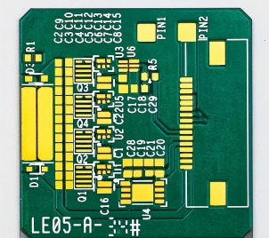
In electronic engineering, signal integrity refers to the measure of the quality of an electrical signal as it travels from a transmitter to a receiver. In a perfect, theoretical system, a digital signal sent as a sharp square waveform would arrive at its destination with the exact same shape, timing, and amplitude.
However, in real-world circuit design, signals are bound by the laws of physics. As high-frequency pulses travel through copper traces, they encounter resistance, capacitance, and inductance. Signal integrity is the rigorous engineering discipline of mitigating these parasitic effects. It involves ensuring that the electrical signal arrives cleanly, without amplitude distortion, unwanted noise, or timing delays. For an optical sensory system, maintaining signal integrity means the raw data representing a concrete barrier reaches the central processor exactly as the sensor captured it.
In consumer electronics, poor signal integrity might result in a dropped Wi-Fi connection or a brief glitch on a monitor. In the context of autonomous driving, the stakes are fundamentally different. A delayed, distorted, or heavily attenuated signal within the internal circuitry can lead to catastrophic miscalculations.
Consider a scenario at highway speeds. If signal reflections or timing jitter corrupt the data stream, the system may generate a ghost object. This false positive occurs where the car detects an obstacle that does not exist, triggering sudden, unwarranted braking. Conversely, severe signal loss could result in a false negative. The data representing a real physical obstacle degrades before processing, causing the vehicle to completely miss a pedestrian. Consequently, preserving perfect data transmission is directly and undeniably correlated with passenger safety.
Modern automotive sensory systems are continuously pushing the boundaries of resolution and range. This evolution inherently requires operating at very high frequencies. The data transmission rates between the sensor array and the analog-to-digital converters often operate in the multi-gigahertz spectrum.
At these extreme frequencies, the circuit board no longer acts as a simple wire; it functions as a broadband transmission line. Standard materials suffer from the skin effect and high dielectric loss at gigahertz frequencies, causing the signal's amplitude to drop significantly over distance. A circuit board must utilize substrate materials that naturally resist these high-frequency attenuation effects. Utilizing a high-frequency ceramic PCB for LiDAR ensures broadband signals remain robust from end to end.
Impedance is the effective resistance of an electric circuit to alternating current, arising from the combined effects of ohmic resistance and reactance. In high-speed digital routing, maintaining a uniform impedance along the entire length of the trace is critical. Engineers typically aim for 50 ohms for single-ended traces or 100 ohms for differential pairs.
If the trace width varies by even a fraction of a millimeter, or if the underlying substrate's dielectric properties fluctuate, an impedance mismatch occurs. This mismatch acts like a physical wall, causing a portion of the high-frequency signal to reflect back toward the transmitter rather than moving forward. These reflections collide with incoming signals, creating destructive interference and corrupting the data. Ceramic substrates provide the dimensional stability and uniform material composition required to maintain extremely tight impedance tolerances.
Sensor circuit boards are incredibly dense. To keep the module compact enough for seamless vehicle integration, engineers must pack laser drivers, photodetectors, amplifiers, and microcontrollers into a very small footprint. This density introduces the severe risk of crosstalk. Crosstalk is a phenomenon where the electromagnetic field from one high-speed trace couples with an adjacent trace, injecting unwanted noise into the neighboring signal.
In addition, an autonomous vehicle is a harsh, noisy electromagnetic environment. The board must shield its sensitive internal signals from external electromagnetic interference generated by electric vehicle traction motors, radar modules, and wireless communication antennas. The substrate material and the board's layer stack-up must facilitate excellent grounding and shielding techniques to prevent both internal crosstalk and external interference from compromising signal integrity.
Recent industry analyses regarding signal integrity demands in autonomous driving reveal a decisive pivot away from organic polymers across the automotive supply chain. The autonomous driving sector is rapidly transitioning from bulky mechanical spinning units to sleek solid-state sensors integrated directly into vehicle bumpers and headlights. As channel counts increase to achieve higher point-cloud density, the thermal load within these compact units skyrockets.
Market trends indicate that Tier-1 automotive suppliers are increasingly mandating specialized inorganic substrates to meet strict Automotive Safety Integrity Level D requirements. Engineers now widely recognize that thermal-induced signal jitter is a primary bottleneck in achieving Level 4 and Level 5 autonomy. Consequently, the adoption rate of advanced ceramic packaging is accelerating. The industry is moving toward materials that not only provide electrical insulation but actively contribute to the thermal and mechanical stability of the entire sensor suite, ensuring fail-safe operation over a 15-year vehicle lifespan.
The dielectric constant, or relative permittivity, of a PCB substrate dictates how fast an electrical signal travels through the copper traces. For high-speed data, not only does the dielectric constant need to be relatively low, but more importantly, it must remain highly stable.
Ceramic materials, such as Alumina and Aluminum Nitride, exhibit a remarkably stable dielectric constant across a wide spectrum of frequencies and extreme temperature variations. Unlike polymer-based boards that experience shifts as the material heats up, ceramics maintain their electrical characteristics. This unwavering stability ensures that the signal propagation speed remains constant and predictable, virtually eliminating temperature-induced timing errors in time-of-flight calculations.
The dissipation factor, or loss tangent, measures how much of the electromagnetic signal's energy is absorbed by the dielectric material and lost as heat. In high-frequency applications, a high dissipation factor results in severe signal attenuation.
Ceramic substrates boast an ultra-low dissipation factor compared to traditional PCB materials. Because the ceramic material absorbs very little of the high-frequency signal's energy, the electrical pulses travel across the board with maximum efficiency. This exceptionally low insertion loss is vital for preserving the weak return signals captured by the photodetectors before they can be amplified and digitized.
There is a direct, undeniable relationship between heat and signal degradation. As temperature rises, the electrical resistance of copper traces increases, and the dielectric properties of standard substrates shift. High-performance systems utilize powerful laser diodes that generate concentrated, rapid bursts of thermal energy.
Ceramic boards provide an elegant, built-in solution through their unmatched thermal conductivity. While FR4 maxes out around 0.3 W/mK, Alumina offers around 24 W/mK, and Aluminum Nitride can reach up to 170 W/mK or higher. This allows the ceramic substrate to act as an active heat sink, rapidly dissipating heat away from the sensitive laser diodes and processing chips. By preventing localized hotspots, the ceramic board keeps the operating temperature stable, thereby fiercely protecting the integrity of the high-speed signals.
When engineers design systems for autonomous driving, material selection is not merely a matter of cost optimization; it is a critical safety decision. To understand why traditional materials fail and ceramics succeed, it is essential to compare their fundamental physical and electrical properties objectively.
| Performance Metric | Standard FR4 PCB | Ceramic PCB Alumina / AlN | Impact on Signal Integrity |
|---|---|---|---|
| Thermal Conductivity | 0.25 - 0.4 W/m·K | 24 - 230 W/m·K | Ceramics dissipate heat up to 100x faster, preventing thermal noise and signal distortion. |
| Dielectric Constant | ~4.5, Varies significantly with heat | ~9.0, Highly stable across temperatures | Stable constant in ceramics ensures consistent signal propagation speed without timing delays. |
| Dissipation Factor | 0.015 - 0.020 | 0.0001 - 0.002 | Ultra-low factor in ceramics minimizes signal insertion loss at high frequencies. |
| Coefficient of Thermal Expansion | 14 - 17 ppm/°C | 4.5 - 7.5 ppm/°C | Ceramics match the expansion of semiconductor components, preventing micro-cracks in solder joints. |
| Mechanical Rigidity | Moderate, Susceptible to warping | Extremely High | Ceramics maintain structural integrity under severe automotive vibrations. |
Autonomous driving systems are subjected to brutal environmental extremes. A sensor mounted on a vehicle's exterior must function flawlessly in sub-zero winters, blistering summer heat, and the radiant thermal loads generated by the vehicle's own engine. When FR4 is exposed to these high temperatures, its epoxy resin begins to soften. The dielectric constant fluctuates, altering the impedance of the transmission lines and causing immediate signal reflections.
In contrast, integrating a ceramic substrate ensures exceptional thermal stability. Because the material properties of ceramics do not degrade or fluctuate under high thermal loads, the signal integrity remains pristine. The data transmitted to the vehicle's central processing unit is accurate and entirely free of thermal-induced noise.
The automotive industry operates on strict reliability lifecycles. A passenger vehicle is expected to operate safely for over a decade, covering hundreds of thousands of miles. During this lifespan, the electronic components endure constant mechanical vibration, shock, and thermal cycling caused by continuous heating and cooling.
FR4 has a relatively high coefficient of thermal expansion. Over thousands of thermal cycles, the mismatch between the expanding FR4 board and the rigid silicon chips creates severe mechanical stress on the solder joints. This eventually leads to micro-cracks and catastrophic signal loss. Ceramic circuit boards, however, boast a low expansion rate that closely matches that of the semiconductor components. This thermomechanical harmony ensures that the physical pathways of the signals remain flawless over the vehicle's entire lifespan.
Transitioning from traditional substrates to ceramic materials requires engineers to adopt specific design methodologies. While ceramics offer superior electrical baselines, maximizing their potential for signal integrity requires meticulous layout planning.
In high-frequency systems, the physical layout of the copper traces directly dictates the quality of the signal. At frequencies operating in the gigahertz range, electrical signals behave like electromagnetic waves. Any sudden change in trace geometry causes an impedance mismatch.
Eliminating Sharp Angles: Traces should never be routed using 90-degree angles. Sharp corners increase the effective width of the trace, causing a localized drop in impedance. Engineers must use smooth curves or 45-degree chamfered bends.
Minimizing Trace Length: High-frequency signals lose energy over distance. Traces connecting the photodetectors to the transimpedance amplifiers must be kept as short as physically possible to minimize insertion loss.
Crosstalk Mitigation: Designers must implement the 3W Rule, spacing traces at least three times the width of a single trace. Utilizing ground pours and shielding vias isolates sensitive signal paths from noisy adjacent lines.
Not all ceramics are identical. Selecting the appropriate base material is a critical design choice that impacts both performance and manufacturing costs. Based on industry-leading capabilities, engineers typically choose between two primary options for LiDAR ceramic substrates.
Alumina: Offering excellent electrical insulation, a stable dielectric constant, and thermal conductivity around 24 to 30 W/m·K, Alumina provides an optimal balance of high-frequency signal integrity and cost-efficiency for standard modules. Modern fabrication allows for ultra-fine line widths down to 50 micrometers, supporting high-density component placement.
Aluminum Nitride: For advanced, long-range forward-facing sensors that utilize highly powerful laser arrays, thermal management is the absolute limiting factor. Aluminum Nitride delivers an astonishing thermal conductivity ranging from 170 to 230 W/m·K. By utilizing Aluminum Nitride, engineers can drive lasers at maximum power without risking thermal runaway or signal distortion.
Designing a flawless schematic is only the first step. Manufacturing a high-frequency ceramic board requires specialized equipment, precise chemical processing, and rigorous quality control. Traditional PCB fabricators often lack the tooling required to metallize and drill ceramic substrates accurately.
The autonomous driving sector is heavily regulated. When vetting a PCB manufacturer, the most critical prerequisite is the IATF 16949 certification, the global quality management standard for the automotive supply chain. Furthermore, the manufacturer should have a deep understanding of functional safety standards like ISO 26262, providing full material traceability and detailed failure mode and effects analysis to ensure the boards meet the required safety levels.
You cannot guarantee signal integrity without empirical measurement. A reputable manufacturer must possess in-house laboratory capabilities to validate the high-frequency performance of the bare boards before assembly.
Time Domain Reflectometry: Essential for verifying strict impedance control. It sends a fast-rise-time pulse through the traces to ensure impedance remains uniform.
Vector Network Analyzer Testing: Measures the scattering parameters of the board, providing precise data on insertion loss and return loss at multi-gigahertz frequencies.
Automotive Reliability Testing: Includes thermal shock testing, high-temperature operating life testing, and vibration testing to simulate decades of on-road abuse.
In the high-stakes realm of autonomous driving, there is absolutely zero margin for error. Preserving signal integrity is the most critical factor in ensuring that a sensory system accurately interprets the physical world. A delayed pulse or a distorted waveform is not just a technical glitch; it is a potential safety hazard.
A ceramic substrate is not merely an optional upgrade. It is an engineering necessity designed to handle the high-frequency, high-heat realities of self-driving technology. By offering a highly stable dielectric constant, ultra-low signal loss, and unmatched thermal conductivity, ceramics ensure that the massive streams of data generated by optical sensors are processed flawlessly on the road.
Ready to secure flawless signal integrity for your autonomous driving sensors? Encourage your engineering and procurement teams to partner with specialized manufacturers. Explore high-performance custom ceramic boards for autonomous vehicles today to meet strict automotive standards and bring safer vehicles to the market.
Signal integrity dictates the reliability of the data the vehicle relies on to navigate. Sensors generate 3D point clouds by measuring the time-of-flight of laser pulses in real-time. This data directly controls the vehicle's braking, steering, and acceleration decisions in milliseconds. If signal integrity is compromised by distortion, noise, or timing delays, the system may register a ghost object or completely miss a pedestrian. Therefore, preserving signal integrity is fundamentally a matter of passenger and pedestrian safety.
Standard FR4 boards suffer from high signal loss at elevated frequencies due to their high dissipation factor and unstable dielectric constant. A ceramic board possesses an ultra-low dissipation factor, meaning the material absorbs virtually none of the signal's energy. Additionally, its highly stable dielectric constant ensures that electrical signals travel at a constant, predictable speed, regardless of environmental temperature changes. This prevents timing errors and ensures the 3D point cloud is rendered with absolute precision.
Yes. Thermal management is one of the primary reasons engineers choose ceramic substrates. High-power laser diodes generate intense localized heat. Ceramic materials, particularly Aluminum Nitride, have thermal conductivities up to 100 times higher than standard FR4. This allows the ceramic board to act as a highly efficient heat spreader, rapidly drawing heat away from sensitive electronic components. By maintaining a stable operating temperature, the board prevents thermal noise from disrupting the high-speed signals.
Modern automotive systems operate at exceptionally high speeds to achieve high-resolution mapping and rapid refresh rates. The data transmission lines on these boards frequently push into the multi-gigahertz range. Standard organic substrates experience severe attenuation and signal degradation at these broadband frequencies. Ceramics are naturally suited for microwave and RF applications, allowing them to support these ultra-high frequencies with minimal insertion loss and minimal electromagnetic interference.
Absolutely. While bulk ceramics can be brittle, ceramic printed circuit boards are engineered for extreme structural durability. They possess high mechanical stiffness and a very low coefficient of thermal expansion that closely matches the silicon components mounted on them. This means the board will not warp, and the microscopic solder joints will not fracture under the constant mechanical vibration, shock, and severe temperature shifts experienced by a moving vehicle.
Trace routing directly impacts impedance and signal reflections. In high-frequency designs, sharp 90-degree corners create impedance drops that cause signal bounce. Using smooth curves, maintaining short trace lengths, and applying proper spacing rules prevents crosstalk and ensures the laser pulse data reaches the processor without distortion.
At multi-gigahertz frequencies, signals travel along the outer surface of the copper traces due to the skin effect. The choice of surface finish is critical. Standard finishes with nickel layers can introduce magnetic losses and increase insertion loss. Engineers often specify specialized finishes like bare copper or immersion silver on ceramic boards to provide a smooth, highly conductive path that preserves high-speed signal integrity.


